Showing posts with label Warhammer. Show all posts

Wednesday 18 November 2020

The 11th Knight, Raven's call and armies on parade

Knightly extravaganza!

This post is a bit of a mixed bag, with two new knights, a couple of new group shots and some armies on parade WIPs - enjoy!

Shock Manta; 11th Knight of the Court

Shock Manta has arrived!

In my last post, I hinted that I was working on one final Knight to bolster the ranks of the Fisher King.  

Well, Shock Manta is now complete and I'm very pleased to add him to the court.  Ever since the were released, I've been eyeing up the Chaos Knight chassis - their double jointed knees, exposed carapace piping and stylised plating just screamed Fisher King to me!

The concept for Shock Manta was for a kind of deep sea spear fisherman crossed with Murmillo a gladiator!  Murmillo's were famous for their large Ovoid helmets and their asymmetrical shoulder armour.  Although I didn't want to completely strip one shoulder plate from Shock Manta like a true Murmillo, I did decide early on that I wanted two distinctly different shoulders.

As for the spear fisherman look, I think that's fairly self explanatory, although I'm glad I went with the t-strike gauntlet to help him reload his giant spears as it gave rise to the spear hopper at the back as well!

All in all, I think Shock Manta has a very unique look while still dropping seamlessly into the army - I hope you enjoy the pictures!

Shock Manta pauses for a moment to take in the majesty of Corbenic's mighty oceans

Shock Manta's giant speargun, resting at his hip

The stilt-like double jointed Chaos Knight chassis really suits my household; good for wading in the shallows while on the hunt

From behind you can see the gigantic extra spears held in the hopper clamps until needed

Shock Manta is already clutching a double-pointed spear ready to load into his cannon after loosing his first deadly bolt

The carapace mounts a double harpoon cannon which started life as a pair of pistons and some Ambot armour!

The large grilled face plate protects the knight's delicate sensors and augers

Like the other knights in the court, Shock Manta has large engine filters instead of smoke stacks, allowing him to be fully submerged without flooding the knight's engine

Another view of the spear clamps - you can also see the large hoist which is used to help service and re-arm the knight

Shock Manta has a normal Thunderstrike Gauntlet, but with the digits from the Chaos Knight kit.  They needed a little alteration as the Chaos Knight is right-handed.

I made the half-mail shoulder pad with actual metal links.  This was by far the most complicated and time consuming part of the while build, but it looks fantastic!


Shock Manta's base was actually made with a combination of techniques which I had learned from making all of my other knights.  I think the frothing waves are especially convincing!

I was especially pleased with the weathered platform which the knights is standing on and the way that it transitions into the rocky beach behind

Veles Meridian - Knight Scion

What Knight of the court would be complete without a Scion pilot?  Meet Veles Meridian!

Veles Meridian eats fish and chips while waiting for orders

To tie him in with his mount, Veles has two mechadendrites extending from his carapace, just like Shock Manta!

Veles' left hand has been replaced by a vicious looking claw.  There are many rumours on how he lost his hand, including a fist fight with a herellion devil squid.  Whatever the truth, he's very tight-lipped (voxed?) on the subject...
Veles is adorned with packs and cases for maintaining his knight's systems while away on mission

Veles is never seen without his signature shock rifle

Veles Meridian - not the best at handshakes

Shock Manta WIPs

Veles Meridian before painting - many kits died so that he may live...

I started the build for this knight by constructing the base platform and cliff face so that I could then build the legs to fit.  I cut and repositioned the front toe on the right foot so that it was 'gripping' the edge of the platform. Go go monkey feet!
While building the knight chassis, I couldn't glue him to the platform as I needed to be able to detach him and the platform in order to sculpt the waves and cliff face.  I lost count of the number of times he toppled off the edge of the table...

I carved four spearhead variants and chose the brutal looking 'classic' spear to go in the gun barrel

As I've documented the process of how I create realistic resin waves before, I won't go through it all again.  Suffice to say that I sculpted, silicone moulded then cast the waves in resin as I have done for my previous projects

As with all members of the court, I applied all of the rust, weathering, verdigris and texture over a silver basecoat.  This is always a scary stage, but I am more confident that it will all be ok in the end now!  I also like that it makes them look like Talos the bronze statue from Jason and the Argonauts...

I always start the detailing by painting the trim and other gold details.  Next I give all of these areas a heavy fleshshade wash followed by some very strong verdigris (sotek blue watered down with nihilikh oxide) then carefully paint the coloured plating in their block colours

Because I start with the weathered metal, I can deliberately apply the armour paint so that some of the layer underneath is showing here and there

I work back into the most damaged rusty areas with more paint and texture where I think it's needed

I apply decals before I work back into the weathering to make sure that they receive chipping and water staining with the rest of the armour plating
I test fit the sub assemblies several times while painting just to make sure that the highlights and weathering are consistent

As I had just completed Veles Meridian, I used the opportunity to take a rather self-indulgent picture of all 11 knight scions together - I love these guys and girls so much!!


Armies on Parade

Due to Covid-19 lockdown measures here in the UK, the Court of the Fisher King hasn't yet made the trip to Warhammer World for a guest exhibition as planned.  Obviously I'm disappointed, but the display should still happen at some point next year once the world rights itself again!  While Covid measures have limited many things, Games Workshop have moved with the times and have shifted Armies on Parade to an online competition this year.  As I've already constructed an army, I decided that I should make it eligible for the competition and make an entry!

In order to compete, I needed to make a display board for the army.  I wasn't happy to simply display my themed army on an unconnected board, so I set about designing one which would not only incorporate all the bases of my knights, but combine them into one cohesive display piece.

First of all, I created a paper template, then cut an MDF board for the Knights.  I settled on the 22" X 30" board space allowed by the rules of the competition.  The knights at the back would need to be elevated to allow them all to be seen at once.  The bases also dictated the placement of half of the knights.  Although I had kept the waves and platforms consistent throughout the builds, they were at different heights.  I'd need to be a bit creative to make this work...

I used extruded foam and a hot glue gun to bulk out the basic shapes so that I could start testing the knight positions
Using the patented 'books for extra height' technique, I marked out the areas which needed to be adjusted

I sculpted all of the rockfaces with a knife and cut the base holes for each knight individually for optimal height matching!

From lower down, you can see that the display is very tall as it has three separate levels for the knights!  I did some basic gap filling which has now fully dried. Next I'll be working on texturing and detailing. Look out for updates soon as I only have two weeks left to get my entry in!

The ranks of House Raven swell!

Finally, I wanted to show some pictures of my most recently painted House Raven Knight Paladin, Cognis.

Cognis is seen here, bracing himself to fire off a salvo from his rapid fire battle cannon

Adhering closely to the House Raven livery, Cognis is a far cleaner and more uniform beast than anything in the Court of the Fisher King!

Cognis proudly sports the yellow, black and white hazard stripes which are synonymous with House Raven

Cognis is decorated with many honour badges, kill markings and purity seals

Although the style and colouring of my Raven Knights is always the same, I take the opportunity to move the hazards to different areas on each knight for some visual distinction between them
Cognis displays the symbol of Legio Metalica on his knee plate, confirming his allegiance to his princeps brothers

I used a spare Magaera head for Cognis as it fits the Questor Mechanicus theme very well

Arbiter, Cognis and Rygan stand ready

And all rejoice with the arrival of their beefy brethren, Siegbreaker

Although different, the knights work well as a cohesive battle force

The variety in carapace markings is more apparent when the knight are viewed from above

Monday 24 August 2020

Imperator Titan Build - Mega Update 2

Body Building

Since my last update, I have tried to concentrate on two main areas; the body and the legs.  My number 1 goal is to have this beast standing over the next couple of weeks.  A number of annoying hurdles have slowed my progress including the weather, constantly running out of  glue / resin / knife blades etc, my jigsaw giving up the ghost and real life just generally getting in the way!

But I am back on, full steam ahead with the project again, putting aside as much time as possible to get Ira Metallum (Yes, I finally chose a name!) standing on its own two feet!

As this is such a huge build project, I am still trying to break it down into sub assemblies and will cover these off individually so that you can get an idea of the amount of effort that has gone into the build so far. 
Almost all of the superstructure elements are complete.  I'm excitingly close to starting the detailing stages!

Pelvis

Since getting the first leg cut out, I knew that the next big challenge was constructing the pelvis in such a way that it could take the weight of everything above it but still only connect to the legs via the hip joints.  I decided that I would use some heavy duty gutter piping sockets built into the foamex in layers to ensure that it was super strong and capable of load bearing without warping or breaking.

While choosing the connectors, I also spent a while walking around the hardware store looking for a receiver which I could build into the legs to simulate a ball and socket joint.  Once I had a solution which I was happy would work, I started designing the pelvis in slices as it would be assembled like a loaf of sliced bread.

While drawing up the templates for the pelvis, I made sure that I checked how it would fit with the pipe connector
The template on the right would be used to create the outer section housing the joint while the left would be used for marking out the staggered central groin assembly
Once I had the basic templates marked up, I stencilled out the corrected number of each part onto 10mm Foamex then set about cutting the components with my trusty (now sadly deceased) jigsaw.

It took me 2 hours to cut out all of the pelvis components and the second leg.  My jigsaw died 2/3 of the way through and I had to borrow one from my neighbour to finish off! Thanks Ryan; the Omnissiah approves! 
The holes for the pipe connectors had to be cut by hand with a knife as the jigsaw would be too rough
Copious test fits were required before gluing the components together.  In this picture, I was testing the rough curve on the front of the groin which would be finished with filling and sanding.
This is the final test fit with all of the slices immediately before I started fixing them together
This is the flip side of the waist which the pelvis would be fixed to once I was happy with the sub assemblies.  There is a very large square 'socket' on this side which the body slots into rather snugly - it's also about 4cm deep so there's no concern over it popping out by accident
This is one of the chunky plastic gutter pipe connectors which I am using for the main pelvis > hip connection
It took a while to cut the hip socket holes as I needed them to be as tight as possible!
The pipe connector was inserted through the outer pelvis sides to a depth of 3cm 
A 3mm countersink layer was then added to house the lip of the connector which prevented it from pulling out of the structure.

I placed angled screws inside the connectors to prevent them from turning then fixed it all in place with 2 part epoxy glue
   Finally a 5mm 'capping plate' was screwed and glued to the inner facing, locking the pipe connector solidly in place on each of the two outer pelvis sections. 
 I glued the central structure together and then attached a positioning block to the waist section to anchor everything on the final assembly.
All 4 sections sat together very nicely without support - a sign of good weight distribution!
It looks a little rough here, but I'd be filling the parts prior to assembling them
From behind, you can see how the anchoring blocks helps me to line up all of the components.  It was also added because I wanted the rear of the waist and pelvis to line up so that I could add the iconic arches from the original model later on
The pelvis flipped upside down so that I could get an idea of whether it looked 'right'
Once I was finally happy with the basic sub assemblies, it was time to fill them - I use car body filler as it's very hardy and can be sanded to a fine grade.  I was a little out of practice with the filler as you can tell by the rough texture!  This didn't worry me too much as I would be using power tools to sand it down once fully cured
And here is the pelvis all sanded and assembled!  I didn't take any pictures of the sanding process as it was dull, very messy and my hands were shaking like a leaf after holding the sander for over an hour...
Here's the pelvis attached to the torso from underneath where you can see some of the minor details I have already added to the underside of the carapace.

Legs

The legs have definitely been the most challenging part of this whole project.  They have been the most complex from a design point of view given that they have to function in universe, but they also had to be structurally sound and be able to hold the weight of the entire titan without buckling.  Just to remind you, this 'miniature' will be 130cm (just over 4 feet in old money), which is double the height of a Forgeworld Warlord class titan.

In terms of weight, although I have kept the materials super light where possible, his body and carapace weight as much as my Reaver and 2 Warhounds, so it wasn't a small consideration!  With that in mind, I made the decision to avoid detailing any of the leg sections until it was all structurally sound - as such, the images below may appear a bit dull, but this stage is pretty critical to the build and I didn't want to deviate from the core structure until it was appropriate...
These are the freshly cut sections which make up the second leg (thighs, knees and calf sections)

In this gratuitous cankle image, you can see the large knee receiver which the thigh section plugs into.Once I am happy with the final position of the knee joints, I will be pinning them in place before covering the outsides with nice detail caps  
This is the first leg after basic filling and sanding being test fitted with the shin and foot.  So far so good...
As I have already covered the build of the first shin, I didn't bother photographing the second one during the process, but here they are together ready for the hip build

Hips

I know that the hips are technically part of the legs, but it's probably the single most important part of the build from a posing and structural point of view, so decided to cover the hips off separately.

As per the image above, I had settled on semi-flexible white pipe covers for the hip receivers which would be built into the legs.  I cut rings to house the caps and glued these together.

This is how the rings looked after screwing them into the thigh and setting the cap in place with glue.  Note that I keyed all of the surfaces for better adhesion prior to assembly
Side view of the basic socket before sculpting

I added two screws for more strength then filled the central anchoring hole with Milliput, making sure that I kept it neat as the black pipe connector would need room to pivot inside for posing
I sculpted a nice curve around the rim of the hip connector with more Milliput and added 4 ball sockets for the actuator pistons I'll be adding later
Here's the hip socket after light sanding - ready for testing!

Hip with inward tilt
Hip in neutral
Hip with outward tilt
My lovely assistant holds the knee joint so that I can test the leg and hip!
Now all I need to do is get the second hip built so that I can work out the final pose!  I deliberately haven't completed the build of the second foot yet as I am still debating over whether I can remove and reposition the toes without compromising the strength of the whole thing!  My gut says it can be done, but until I can do a dry fit with all of the parts, I will hold fire on that particular decision!

Caparace Arches

Although I have staunchly avoided adding details to anything which is likely to change during structural tweaks, I allowed myself a whimsical treat in the form of arch detailing for the carapace rim.  I'd already decided to reproduce the iconic arches from the original epic miniature, so I set about deciding how I'd produce so much detail in an acceptable amount of time!

I settled on a modular design which I could cast into resin, which would allow me to add parts for variation but remained consistent.  I measured each stretch of carapace and worked out a winning formula for the dimensions of the parts I'd need to produce.  This involved creating a quick template for a single and a triple arch.  In the end, I made two triple arch sections so that I could add even more variety and would require less casting runs as I only wanted to make one silicone mould.

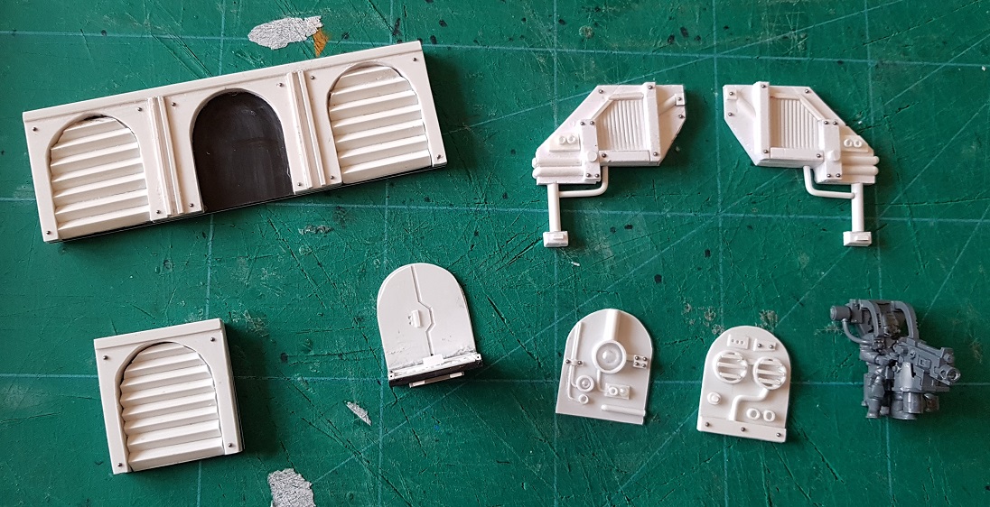
The basic 'vent' style arches were my go to design.  The 3 arch piece had a blank socket for the variable details
Next it was time to start making some inserts...
...one of which started to look quite familiar!
Eventually arch insert 1 with its double fan was finished
Then came arch insert 2 with it's optics
Finally came arch insert 3 which was to form the basis of my titan's light point defence with an access hatch and a socket for...
...a heavy bolter with gunner!
From above you can see that the little platform has a little connector for the gunner harness
I have six of these 'door gunners' which will eventually be fixed to the edges of the carapace to provide anti-personnel fire 
As well as the arches, I also decided to add in some general surface detail elements which I could use as necessary during the final detailing stages.  These greebles would give me a little pool of parts to draw on when I needed them later
Once I was happy with the second triple arch and 'random greebles', I glued them all to a backing plate and filled any gaps with green stuff to prevent the silicone from getting into or under the parts
I also painstakingly added 1mm ball bearings for rivets
Once I was happy with the final detail plate, I built mould walls and sealed all of the edges to make it water proof and avoid leakage
I then mixed up and poured in the silicone...
...and hey presto! 24 hours later, I had a workable mould!
I cleaned up the mould flash with some nail scissors and gave it a very light coat of vaseline mould release
I worked out the volume of resin I'd need using water in my pot, then measured out the resin by weight as per the manufacturer's instructions (always make sure you don't confuse volume with weight...)
And here is my first casting!  In truth, it wasn't a great cast, but without a vacuum chamber, it's difficult to get a better result!
In the end I did 8 castings which gave me enough to trim the entire carapace with several left over in case I needed spares
After a couple of hours, I'd cleaned up all of the arches and was ready to start attaching them!
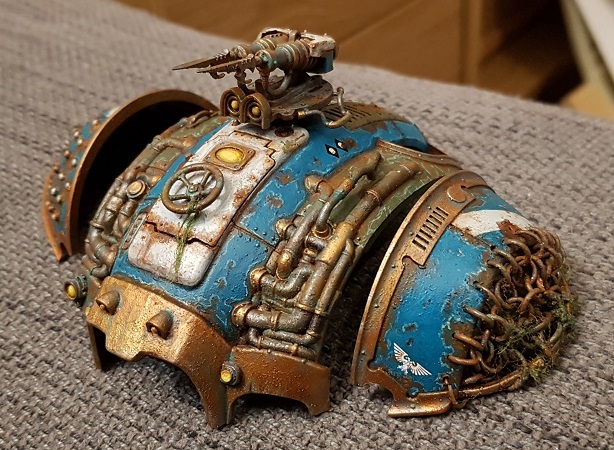
And here they are in situ!
From the side you can see the placement of the door gunner platforms
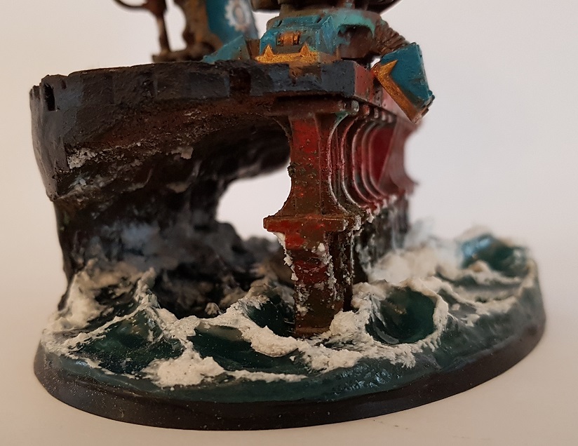
The rear section has a large gap which is where the lower section of the macro cannon tower passes through the carapace and links up with the power plant underneath 

And that's all for now folks!  Hopefully by the next time I post an update, Ira Metallum will finally be standing!