Since my last post, I've managed to get quite a lot of the remaining Tantalus build work done. I'll go through my progress one stage at a time just in case anyone wants to follow the project in its entirety!
The Hull
I'm not going to lie to you - the hull has been really hard work! I think having the blog to update spurred me on as this was a really tough stage of the build. Having the Hobby beaver looking over my shoulder helped motivate me too...
To begin with, I cheated. When I say cheated, I mean that I measured the height of the tallest ribbing and went on t'internet to order styrene strips of the correct height and width.
This saved me a huge amount of time and effort - having scratch built things from nothing but sheet styrene in the past, I know the toll it would have taken on my fingers!
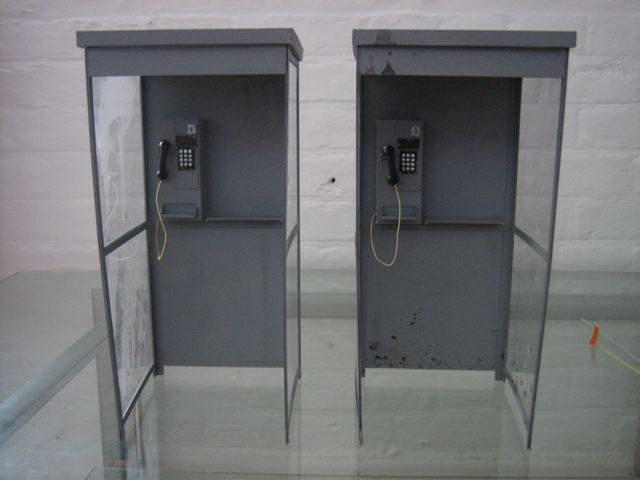
A good example of this are some 1/6 scale phone boxes I built from scratch some time ago. Every single strip was measured and cut from a single Styrene sheet. I struggled to hold a mug for the following week while my fingers recovered!
 |
| Components from the two Phone booths with assembled back plates |
 |
| Finished assembly |
 |
| One of the booths in situ on a miniature street. Convincing huh? |
Anyway, once the styrene lengths arrived, I measured the blank areas on the underside of the hull then cut a ridiculous number of individual lengths to the correct size and painstakingly glued them in place taking care to space them equally for the ribbing.
I did noticed a small amount of spacing variance once I'd completed this stage, but as it was on the underside of the hull, I decided not to re-set all of the ribs as it took me a couple of hours to do it the first time!
Top tip: Styrene and ABS are not like the standard GW grey plastic when it comes to creating a bond with polystyrene cement / liquid poly. It tends to form a glossy surface bond rather than having a substantially deeper chemical reaction. Keep this in mind as if you are gluing styrene, you will always need to use plenty of twisting motions to encourage the surfaces to adhere and achieve a solid bond. Keying the surfaces prior to gluing also helps. If you don't do this, you risk the parts separating neatly and destroying your hard work!
Once I'd got the ribbing in place and given it a little while to dry, I used a Sharpie to accurately mark out the areas where I would need to work on the styrene bars to bring them in line with the existing Raider contours.
The tools I used to sand down the contours were pretty straightforward, but I'll list them anyway!
- Convex file
- Emery board
- Medium gauge sandpaper in little squares
- Some round plastic tube cut to a convenient length
This final tool was actually the most important part as I specifically chose a piece which would help me achieve the correct curvature evenly across the hull.
 |
| Tools. Exciting. |
 |
| I wrapped the sandpaper around the tube and used some tape to keep it in place. |
 |
| Carefully sanding down the hull ribbing while watching Taskmaster on the telly. |
 |
| You can see the contours slowly taking shape! |
At this point, I'll refer you back to the aforementioned top tip. It's so important. I had several ribs detach during sanding and it was a complete ball ache to get them stuck back in place while covered in a thin layer of dusty plastic particulates.
Meanwhile on the topside, I used the tube and paper to sand down the outer plating which I had filled in a couple of days before with putty. I used the file tip at this point to redefine the plate divides as they wore down a little during sanding. The result is a nice smooth join between the plastic and putty.
 |
| Extended hull being sanded down and sharpened up |
I like to use a putty mix for hard surfaces like these - it's 80% Milliput silver/grey and 20% greenstuff. The Milliput in the mix gives a very strong surface for sanding once cured, while the green stuff removes some of the crumbly, tackiness from the Milliput while you're handling it.
I use silicon based hand cream on the surface of this mix while it's still curing to smooth it out.
I always tend to do bulk areas with cheap tough Milliput and green stuff then add surface details with Procreate putty. Procreate is my favourite putty for many reasons, but it's more than twice the price of anything else, so I use it sparingly!
The eagle eyed among you will notice that the cannons at the front have been removed. This was not intentional. The bloody things snapped off several times until I decided to leave them off. Once I'd finished all of the rough work on the hull, I drilled and pinned them in place. Nothing short of a natural disaster will snap the little bastards off now!
Rudders
Whilst I had the rudders prepped and ready for some time, I held off attaching them until I had worked out the base. The reason for this was the relative fragility of the rudder assemblies. After my experience with the nose cannons, I decided to hold off until the elevated stand was ready. Putting the hull on a flat surface would snap the rudders off straight away and I didn't really want to have a rage fit in front of the kids!
 |
| First rudder in place, pinned to the hull. |
 |
| Why take one rudder into battle when you can take three?! |
The Sail
Given that the sail is quite large, I decided early on to make it from a single relatively thin styrene sheet and add the ribs as surface detail using semi-circular styrene dowel. This was actually more straightforward than I had anticipate as I carefully measured, cut and pre-curved the ribs before gluing them in place.
The connectors and point caps were more difficult to attach and did require a lot of pinning and patience as the main connector frame would be taking the weight of the whole sail at a fairly severe angle! Taking my time on this section definitely paid off!
 |
| Final sail assembly complete! |
The sail is attached to the mast with a small metal pin which goes down into the mast past the first knuckle joint. For added strength, I also drilled up through the bottom of the hull and put another 2cm metal pin up through into the mast.
 |
| The sail finally in place! |
Believe it or not, the sail is only resting on the pin in these pictures (it's not glued in place yet). I see this as testament to planning the structure and strengthening the correct areas during the build!
The Flight stand
I'd been puzzling over the stand for days and eventually decided that the weight of the model and height required to make it look impressive (and avoid snapping bits off!) required more than just a standard flying stem. A normal Games Workshop flight stand was also out of the question as the fulcrum would actually be right in the void between the double hull!
I settled on creating a tripartite stand using ball ended flight stems. I angled two regular stems using the existing Raider hull sockets so that they met over the area where the balancing fulcrum should exist. I then positioned a third longer stem and tested the balance. Thankfully it worked perfectly to support the weight of the model! I created a socket for the third stem under the hull where the mast connected, using some pure Procreate putty. As this area had already been pinned, it was a no brainer for placing the third support!
 |
| Stupid fulcrum void... |
I carefully drilled and pinned the three flight stems together then glued them to a length of plastic dowel. I then 'wrapped' the whole connecting area with some Milliput to add extra strength. I cut a hole through a large oval base and glued the dowel in place. I then used some heavy slate rocks and more Milliput to add considerable weight to the base and strengthen the connection further. This would also counter-balance the weight of the model to prevent it from tipping over!
 |
| Behold the ugliest flight stand at the ball!! |
 |
| Tripartite stand holding the model. Thanks goodness for that! |
Almost there!
I'm now on the final stretch!
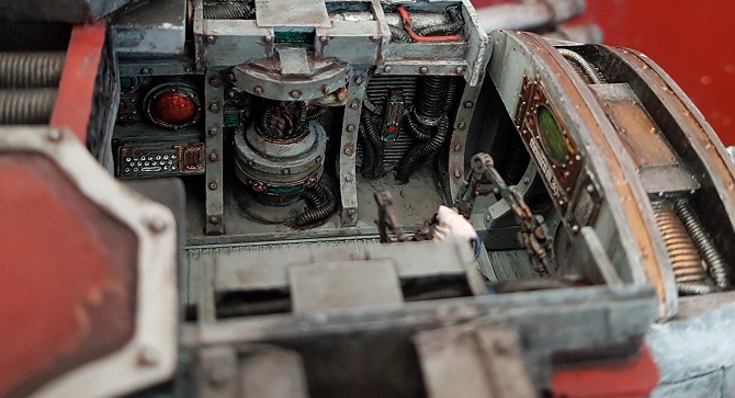
Structurally everything works and personally, I think it's looking amazing! Surface detailing and adding the crew are next on the agenda.
I'll be adding the following finishing touches over the coming days...
- Little spikes and chains on the hull plating
- Haemonculus Coven Wrack crew including control panels
- Rigging (which you'll notice I've already added the hooks for if you look carefully...)
- Large-ish blade vanes under the hull
Following that, it'll be on to painting!
Final thoughts
Although I really love the Forge World kit, the reason I started this project was to make an original looking Tantalus which fitted nicely with my Coven. This was partly driven by the fact that I wanted more decking for my models to be placed on as it'll mainly be carting my grotesques around and they have pretty large bases!
I've put some comparison pictures below - I'd love to hear what you think! :)
 |
| The lovely Forge World original |
 |
| My Tantalus |